Every cell format is important in battery research and development. However, the data obtained from each format must be evaluated within the boundaries defined by its design and the size of the tested electrodes. Uncritically extrapolating the performance of prospective commercial large-area cells from data generated with smaller formats often overlooks issues that become apparent only during scaling up. When going to mass production, such assumptions can lead to a substantial waste of time, materials, energy and money—far exceeding the resources required to produce a small number of commercial-like cells upfront.
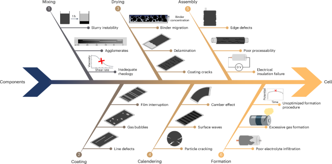
In fact, upscaling new materials or processes developed at laboratary scale presents a series of challenges that are frequently neglected when the objective is limited to producing mAh-scale cells (that is, with TRL ≤3)17,18. As illustrated in Fig. 1, on the way from individual components (active materials, separator, electrolyte, current collector, casing and so on) to the finished cell, problems generally arise during slurry mixing and coating, electrode drying and calendering, and cell assembly and formation19,20. While not having the possibility here to discuss these challenges individually, we want to emphasize that the majority of the issues shown in Fig. 1 has a substantial impact on the battery performance and can be fully detected when assembling Ah-level large-area cells20. However, according to a recent peer-reviewed publication that analysed more than 13,000 scientific publications on batteries, only about 28% of the research articles reporting the electrode composition specify the area of the electrodes21. A related study on the same dataset suggests that even fewer accurately describe the cell format and design (for example, coin cell, pouch cell and so on)22.
We routinely use coin cells (approximately 2–6 mAh) to evaluate the specific capacity, initial coulombic efficiency and discharge rate capability, as they are simple and quick to assemble and test. Typically, for an initial assessment of the Li-ion storage capability, coin cells are assembled using the investigated active materials at the working (positive) electrode and lithium metal at the counter (negative) electrode, along with the same electrolyte solution that is used in upscaling experiments with larger formats. However, the reliability of cycle life data obtained from coin cells is questionable, as it has been shown to depend on highly variable parameters, such as the type of casing steel and the applied pressure, that is, the stack height23,24, which are independent of the materials studied. In addition, the misalignment of positive and negative electrodes can easily occur25, and the high perimeter-to-area ratio of small-area electrodes indicates a strong, detrimental influence of the electrodes’ edges on cell performance26. While these issues may still allow researchers to compare the results from coin cells assembled in similar conditions within their laboratories, comparisons of results obtained in different laboratories, where the assembling quality is not known, should be approached with caution. Although coin cells are usually the preferred format for low-TRL studies to characterize new battery materials, they should be considered inadequate predictors of cycling stability in scaling-up studies involving TRL ≥4 cells. Moreover, high-current-rate experiments should also be critically evaluated due to the large resistance of the coin cell set-up and, in the case of Li metal coin cell tests, the overpotential caused by the lithium metal counter/negative electrode, especially when testing working/positive electrodes with high areal capacity23,24.
Single-layer or double-layer pouch cells (approximately 50–200 mAh) are the next-size battery test vehicle in our workflow27. They can be conveniently assembled using a relatively small amount of active material and even hand-coated electrodes. Their larger area allows a more reliable assessment of long-term cycling stability28. These data can be used to infer the behaviour of larger cells, but with some important limitations to consider, such as the still relatively high perimeter-to-area ratio, the impact of the negative electrode overhang size on the total cell area, and a reduced temperature increase during cycling compared with Ah-scale cells12,28. In addition, pouch cells lack standardization in terms of dimensions and area, as they do not have a standardized hard case to constrain their size, unlike cylindrical and prismatic cells. Importantly, multilayer stacked pouch cells, that is, pouch cells whose electrodes are cut in multiple pieces with same dimensions and piled up29, do not ensure that the electrodes used during the assembly are consistently of high quality, as only the best sections of the electrode may be selected and cut for the cell assembly. This issue is reduced in large wound cells, as electrodes with lengths over 1 m are used in Ah-scale cells, which must meet strict production quality standards to ensure reliable cycling data. To ensure the reproducibility of battery testing, it is necessary to assemble a relevant amount of such wound cells where the double-sided electrodes must be homogeneously coated over a length in the order of 100 m to 1,000 m (refs. 12,29). Furthermore, winding induces stress on the electrodes due to the curvature around the cell’s winding mandrel, requiring them to have more stringent mechanical properties (for example, adhesion and cohesion) compared with stacked pouch cells12,30. Wound cell formats typically have predefined casings, such as 18650, 21700, 4680 and so on, for cylindrical cells, or VDA (acronym for Verband der Automobilindustrie, the German Association of the Automotive Industry) PHEV1, VDA PHEV2 and so on, for prismatic cells29. Standardized dimensions facilitate the comparison of energy density and performance across different cells from various research institutions or manufacturers. Nevertheless, they require more advanced equipment for their assembly and cycling, such as winding machines and high-current testing equipment. It is important to notice that, for applied testing currents >1 A, the thermal behaviour and the resistance of current collectors and cell’s connectors start acting as stumbling blocks for the delivery of adequate cell performance, unlike in smaller cell formats, where such high currents are usually not applied.
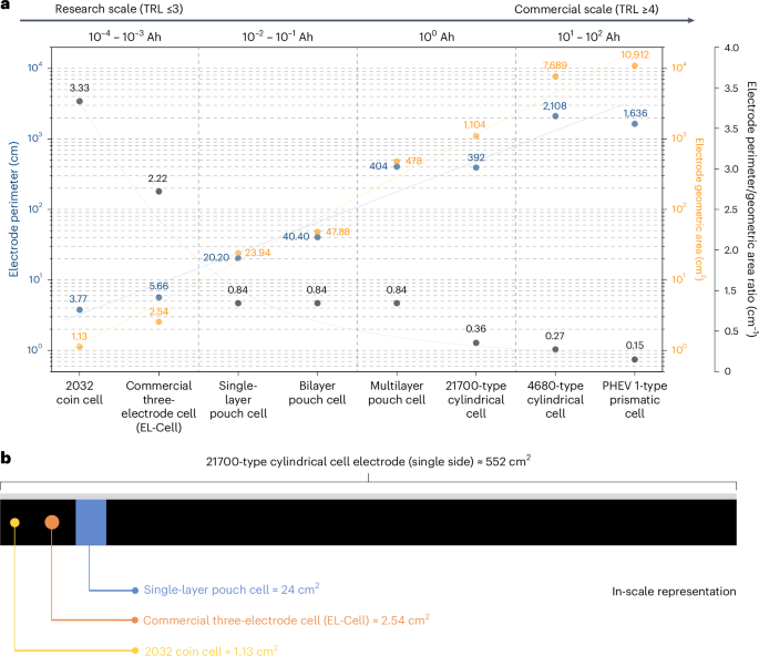
Figure 2a shows the geometrical area and perimeter of electrodes for various types of laboratory-scale and industrial-scale cell configurations we assemble and test. Moving from the left to the right of the graph, it can be noticed how the values of electrode perimeter and geometrical area change when transitioning from basic low-TRL research to high-TRL commercial scale (data and methods used to calculate the geometrical area and perimeter values for each type of cell can be found in Supplementary Note 1). The geometrical area and perimeter span four to five orders of magnitude when transitioning from a 2032 coin cell to a prismatic cell. Whereas only a few square centimetres of electrode are needed for a coin cell, commercial cell formats require large, high-quality, defect-free electrodes to attain the intended battery performance and ensure data reliability. Based on the assumptions used for the calculations for Fig. 2a, 21700-cell electrodes are approximately 1 m long, while electrodes for a 4680-cell measure more than 5 m in length. This means that, for building these large-electrode-area cells, the absence of the issues illustrated in Fig. 1 must be ensured over multiples of these electrode lengths even at pilot scale, not to mention mass manufacturing. In general, regardless of the cell format used, ensuring the coating of high-quality, uniform electrodes should be a primary focus in battery research studies, and it is of paramount importance when aiming to produce and test cells with TRL ≥4.
a, The electrode perimeter (blue), electrode geometric area (yellow) and perimeter/geometric area ratio (grey) for different cell formats. Information regarding the assumed dimensions, number and type of electrodes for each cell format is provided in Supplementary Note 1. The dashed lines serve as a guide for the eyes. b, A schematic illustration with an in-scale comparison of the size of a typical 21700-type cylindrical cell electrode, a single-layer pouch cell electrode and disk-shaped electrodes for commercially available three-electrode cells (EL-Cell) and 2032 coin cells. For the 21700-type cylindrical cell electrode, the area of only one of the two coated sides is reported, for a better comparison with the other single-side coated electrodes.
To better visualize this size difference, Fig. 2b shows a scaled comparison of a typical electrode for a 21700 cylindrical cell versus electrodes for single-layer pouch cells, commercially available three-electrode cells (EL-Cell) and 2032 coin cells. From this schematic, it is evident that the geometrical area of the electrodes in coin cells is very limited compared with those used in cylindrical cells. The same consideration can be applied to electrodes used in single-layer pouch cells. Even in the case of multilayer pouch cells assembled in a stacked configuration, a selection of the most homogeneous negative and positive electrodes is still possible, as the individual electrodes in small-area pouch cells are usually much smaller than those in cylindrical or prismatic cells, where electrodes are wound rather than stacked30. This electrode selection for pouch cell assembly increases the scrap rate and hinders the identification of issues during the electrode production phase. Therefore, large-area, non-stacked cells can more reliably ensure that the used electrodes are free of defects that could negatively affect a cell’s electrochemical energy storage performance.
In Fig. 2a, we also show the electrode perimeter-to-geometric area ratio for each cell format, which can be used to assess the influence of electrode edges on cell behaviour. The edge region plays a critical role in the cell’s stability as it is a hotspot for lithium deposition at the negative electrode during battery operation31. Moreover, cutting electrodes into the desired shape can produce burrs and dust at the edges, increasing the risk of piercing the separator and causing local short circuits30. Therefore, a lower perimeter-to-geometric area ratio indicates better electrode quality and fewer defects. While a 12-mm-diameter coin cell electrode has a perimeter-to-area ratio of 3.33 cm−1, the same ratio for a double-side coated 6 × 92 cm2 21700 cylindrical cell electrode is 0.36 cm−1, about ten times lower. The choice of large-area cells becomes then even more important, as it minimizes the adverse effects of edges on battery performance. With the detrimental effect of the electrodes’ edges, the actual performance of the cell will not align with the intended performance, because a higher number of edges increases the likelihood of defects and, hence, the possibility of triggering of failure mechanisms. We would also like to emphasize that, in the case of multilayer stacked pouch cells, increasing the number of layers (and, therefore, the capacity and area) does not result in a decrease in the perimeter-to-geometric area ratio, as the selected electrodes maintain the same geometric characteristics.


